
Technical Features of Commercial RO Plants, depends on the type of membrane utilized and the quality of the raw water supply, rejection rates of salts from water are typically in the range of 95–99.5%. The variety of membranes are currently available which can be used in the Commercial RO Plants to produce permeate water with a variety of characteristics. Low Energy Membranes, which are used in the production of standard-designed ROs, produce permeate water with a quality of about 10 micro Siemens from input water within a 500–700 micro Siemens range.
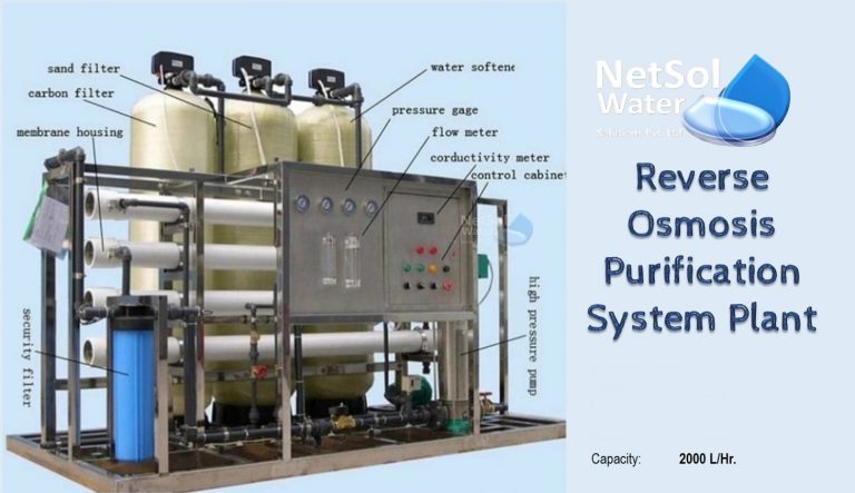
Constituents of Commercial RO Plant
The system typically includes a pressure pump, housing and a membrane. Pure water (or permeate), which is collected and sent to service is forced under pressure into the housing. Reject water (or concentrate) is gathered from another outlet and sent to the drain, with some of the recycled concentrated water going back into the pump’s inlet. As a result, a recovery ratio of roughly 75% can be reached without significantly fouling the membrane because the amount of water that is discharged to the drain is maintained to a minimum. Recirculation enables a higher water flow through the pump, lessening the strain on its bearings and maintaining the pump’s cooler.
Technical Features of Commercial RO Plants
Here is the list of technical features of a commercial RO plants available with Netsol Water in India.
| S.No. | Description | RO Plant Specifications depending upon capacity | ||||
| 250 LPH | 500 LPH | 1000 LPH | 2000 LPH | |||
| 1. | Raw water feed pump | Type | Centrifugal | Centrifugal | Centrifugal | Centrifugal |
| Flow rate | 1500Lt/Hour | 1500Lt/Hour | 2000Lt/Hour | 3300Lt/Hour | ||
| DischargeCapacity | 2.5 kg/cm2(min.) | 2.5 kg/ cm2(min.) | 2.5 kg/ cm2(min.) | 2.5 kg/ cm2(min.) | ||
| Motor Rating | 0.5 HP (min.) | 1.0 HP (min.) | 1.0 HP (min.) | 2.0 HP (min.) | ||
| Electricity | 220 V, Single phase | 220 V, Single phase | 220 V, Single phase | 415 V, Three phase | ||
| Quantity | 1 | 1 | 1 | 1 | ||
| 2. | Pressure Sand Filter (PSF){For capacity below 500 LPH} | Capacity | 1500Lt/Hour | 1500Lt/Hour | NA | NA |
| Min.Operating Pressure | 1.5 kg/ cm2 | 1.5 kg/ cm2 | NA | NA | ||
| Media | Support bed +Carbon | Support bed +Carbon | NA | NA | ||
| Quantity | 1 | 1 | NA | NA | ||
| 3. | Dual media filter (DMF){For capacity above 500 LPH} | Capacity(min.) | NA | NA | 2000Lt/Hour | 3300Lt/Hour |
| OperatingPressure(Min) | NA | NA | 3.5 kg/ cm2 | 3.5 kg/ cm2 | ||
| Type of Valve | NA | NA | Single- multiport | Single- Multiport | ||
| Media | NA | NA | Anthracite+Support Bed. | Anthracite +Support Bed. | ||
| Bed depth(min.) | NA | NA | 800 mm | 800 mm | ||
| Quantity | NA | NA | 1 | 1 |
| 4. | Activated carbon filter (ACF) | Capacity | 1000Lt/Hour | 1200Lt/Hour | 2000Lt/Hour | 3500Lt/Hour |
| Min.Operating Pressure | 1.5 kg/ cm2 | 1.5 kg/ cm2 | 1.5 kg/ cm2 | 1.5 kg/ cm2 | ||
| Media | ActivatedCarbon + sand | ActivatedCarbon + sand | ActivatedCarbon + sand | ActivatedCarbon + sand | ||
| Quantity | 1 | 1 | 1 | 1 | ||
| 5. | Antiscalant Dosing System | Dosing Pump | ||||
| Type | Electro-magnetic | Electro-magnetic | Electro-magnetic | Electro-magnetic | ||
| Capacity | 1.5Lt/hour | 1.5Lt/hour | 1.5Lt/hour | 1.5Lt/hour | ||
| DischargePressure | 4 kg/ cm2 | 4 kg/ cm2 | 4 kg/ cm2 | 4 kg/ cm2 | ||
| Quantity | 1 | 1 | 1 | 1 | ||
| Dosing Tank | ||||||
| Capacity | 100 Lt | 100 Lt | 100 Lt | 100 Lt | ||
| Material ofConst. | HDPE | HDPE | HDPE | HDPE | ||
| Quantity | 1 | 1 | 1 | 1 | ||
| 6. | Micron Cartridge Filter(For removing suspended particles >5 micron) | Capacity | 1000Lt/hour | 1200Lt/hour | 2000Lt/hour | 3300Lt/hour |
| Material of Cartridge | Polypropylene | Polypropylene | Polypropylene | Polypropylene | ||
| Filter Rating | 5 micron | 5 micron | 5 micron | 5 micron | ||
| Length | 10” | 20” | 20” | 20” | ||
| Quantity | 1 | 1 | 1 | 1 |
| 7. | High Pressure Pump | Type ofPump | Vertical Multistagecentrifugal | Vertical Multistagecentrifugal | Vertical Multistagecentrifugal | Vertical Multistagecentrifugal |
| Capacity | 1000Lt/hour | 1200Lt/hour | 2000Lt/hour | 3300Lt/hour | ||
| Discharge Pressure(Max.) | 11 kg/ cm2 | 13 kg/ cm2 | 13 kg/ cm2 | 13 kg/ cm2 | ||
| Material of Construction | SS | SS | SS | SS | ||
| Electricity | 220 V, Singlephase | 220 V, Singlephase | 220 V, Singlephase | 415 V, Threephase | ||
| Quantity | 1 | 1 | 1 | 1 | ||
| 8. | Reverse Osmosis Membrane | Permeatecapacity | 250Lt/hour | 500Lt/hour | 1000Lt/hour | 2000Lt/hour |
| Membrane Type | Spiral wound TFC-polyamide | Spiral wound TFC-polyamide | Spiral wound TFC-polyamide | Spiral wound TFC-polyamide | ||
| Size | Dia. 4’’ X 40’’long | Dia. 4’’ X 40’’long | Dia. 4’’ X 40’’long | Dia. 4’’ X 40’’long | ||
| No. ofMembrane | 1 | 2 | 5 | 9 | ||
| No. ofMembrane Housing | 1 | 2 | 2 | 3 | ||
| Skid Materialof Construction | Mild Steel –Powder Coated | Mild Steel –Powder Coated | Mild Steel –Powder Coated | Mild Steel –Powder Coated | ||
| 9. | UV system | Capacity | 250Lt/hour | 500Lt/hour | 1000Lt/hour | 2000Lt/hour |
| Quantity | 1 | 1 | 1 | 1 | ||
| 10. | Instrument List | A) Pressuregauges | 3 Nos. | 3 Nos. | 5 Nos. | 5 Nos. |
| Range | 0 – 21 bar | 0 – 21 bar | 0 – 21 bar | 0 – 21 bar | ||
| Dial Size | 4 inches | 4 inches | 4 inches | 4 inches |
| B)Pressureswitches | 2 Nos. | 2 Nos. | 2 Nos. | 2 Nos. | ||
| Range | 0-450 psi | 0-450 psi | 0-450 psi | 0-450 psi | ||
| C) Conductivity meter | 1(Panel Mounted) | 1(Panel Mounted) | 1(Panel Mounted) | 1(Panel Mounted) | ||
| D) Rotameter | 2 | 2 | 2 | 2 | ||
| E) Levelswitch | 2 | 2 | 2 | 2 | ||
| F) DigitalTDS Meter | 1 | 1 | 1 | 1 | ||
| 11. | Electrical Control Panel | Starters, overload relays, single/three phase controller for pump | Should be provided of adequate capacity | Should be provided of adequate capacity | Should be provided of adequate capacity | Should be provided of adequate capacity |
| B) Voltmeter, Ammeter, MCB’s | Should be provided of adequate capacity | Should be provided of adequate capacity | Should be provided of adequate capacity | Should be provided of adequate capacity | ||
| C) PLC &Touch Panel | Must be provided | Must be provided | Must be provided | Must be provided | ||
| D) Feed/ Product water conductivitymeter | Must be provided | Must be provided | Must be provided | Must be provided | ||
| 12. | pH Correction Dosing Tank (Optional, as per requirement) | Dosing Pump | ||||
| Quantity | 1 | 1 | 1 | 1 | ||
| Type | Electro-magnetic | Electro-magnetic | Electro-magnetic | Electro-magnetic | ||
| Capacity | 0-1.5 LPH | 0-1.5 LPH | 0-1.5 LPH | 0-1.5 LPH | ||
| DischargePressure | 2 kg/ cm2 | 2 kg/ cm2 | 2 kg/ cm2 | 2 kg/ cm2 | ||
| Dosing Tank | ||||||
| Capacity | 50 Lt | 50 Lt | 50 Lt | 50 Lt | ||
| Material | HDPE | HDPE | HDPE | HDPE |
The Commercial RO system’s controller continuously checks the permeate water’s purity and is connected to the system’s safety controls to make sure the unit shuts down when there is a signal of low or high pressure, high or low conductivity or a full permeate tank. To extend the membrane’s life, several pre- and post-flush cycles are also executed. To guarantee system protection at all times and to maximize the quality of the pure water, we also monitor constantly apart from other monitoring, which is automatic.
Extending the membranes life
Water that has been softened and de-chlorinated must be provided to Commercial RO plants. For continuous operation, a softener is advised. By using softened water as the RO’s feed, you can extend the membrane’s lifespan by lowering the risk of scaling. De-chlorinating the feed will lessen oxidative harm to the membrane’s surface. Concentrate water can be returned to a softened water holding tank if softened service water is required elsewhere on the same installation site, preventing water waste.
To learn more about our wide range of Commercial RO Plants, call us at +91-9650608473 or send an email to enquiry@netsolwater.com.